How to Make Sequence Detectors(Finite State Machines)
Hello friends, this time I came up with a new Article on how to make the State Diagrams of the Sequence Detectors-Finite State Machines(FSMs) and Sequence Detectors. Almost every Computer Science student come across the finite state machines in his/her course, some students may end up with doubts in this subject. Don't worry, in this article I will show you how to make state machines by making a simple Sequence Detector.
What is in this Article:-
1).Basic Knowledge of Sequence Detection
2).How to make State Diagrams?
3).Make State table from State Diagrams and generate State Equations from these table.
4).How to design the FSMs from State Equations using Flip Flops(Here, D-Flip Flops).
Let's Start:-
1). Basic Knowledge of Sequence Detection:-
The Sequence we are going to detect is the 1101 and 1001 With Overlapping. This means that suppose we are given a random binary bit string like:-
110100100001111010000011111000101010111100011010010011011100
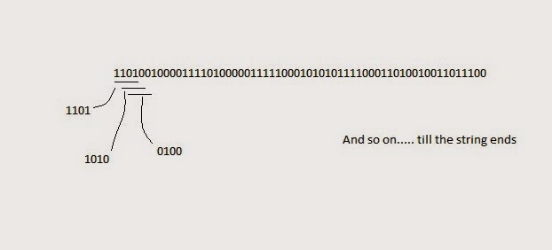
and we have to take each four bit at time and as soon as we detect either 1101 or 1001 then we have to give the output as true or 1, else we have to give out false or 0. And as we are told that check them by "Overlapping" way it means we select each four bit as shown below:-
Image:-
And for each four bits we will give our response like in above given string the response string or the output string of the detector(that we are going to design) after the detection of 1101 and 1001 would be:-
Image:-

So, now you may understood how this is going to be(If not, then please Email me your queries to deepcpatel@yahoo.in or write in form of comments , I will surely reply you). Now we are going design the state diagram for this.
----------------------------------------------------------------------------
2). How to make State Diagram?
First of all, let's think that why do we need the state diagram? For the Computer, the state diagram is like the instruction sets or like some treasure map in which , we are on some initial position and then we have to perform some procedure(here input and check it) to go closer to the treasure(here desired output), and for each procedure we go to next level(here state) and for some wrong step(here wrong input) we may end up to initial place(here state zero). But instead of doing this manually why don't we just make the map for computer and assign it to do our treasure hunt by giving it certain instructions and we just enjoy playing games.
This map for computer is called state diagram. So now you would have understood the real meaning of state diagram, if not then wait until we make it. So then let's start to make it.
1). First of all we have to decide how many states we want in our diagram. If there would be one binary number (like here only 1101 or 1001) given to us then it would be quite easy to decide the number of states, they would be equal to number of bits of the given binary number. But for more than one number we have to analyze them(let's say we have make maps of two distinct routes that lead to same treasure, so that computer can go either way), let's do it.
Analysis:- a). Look that the first bit of both the numbers(1101 and 1001), it is 1 it means that the next level or stage on the both the map(here diagram) is same.
b). Now as second bit of both nos is different(1 and 0) computer now can go to either level so here two levels are required,so here we need 2 more levels, then they lead to two other two levels so we need two other levels.
c). Now as the destination is same the final state would be one.
So, now in total we need 6 states. This was the rough analysis but the real determination of the state will come from experience and practice.
2). Now as we know the number of states in our diagram we will initially name them S0, S1, S2, S3, S4, S5, and at last we will assign them the binary codes.
Image:-


What is in this Article:-
1).Basic Knowledge of Sequence Detection
2).How to make State Diagrams?
3).Make State table from State Diagrams and generate State Equations from these table.
4).How to design the FSMs from State Equations using Flip Flops(Here, D-Flip Flops).
Let's Start:-
1). Basic Knowledge of Sequence Detection:-
The Sequence we are going to detect is the 1101 and 1001 With Overlapping. This means that suppose we are given a random binary bit string like:-
110100100001111010000011111000101010111100011010010011011100
and we have to take each four bit at time and as soon as we detect either 1101 or 1001 then we have to give the output as true or 1, else we have to give out false or 0. And as we are told that check them by "Overlapping" way it means we select each four bit as shown below:-
Image:-

Image:-

So, now you may understood how this is going to be(If not, then please Email me your queries to deepcpatel@yahoo.in or write in form of comments , I will surely reply you). Now we are going design the state diagram for this.
----------------------------------------------------------------------------
2). How to make State Diagram?
First of all, let's think that why do we need the state diagram? For the Computer, the state diagram is like the instruction sets or like some treasure map in which , we are on some initial position and then we have to perform some procedure(here input and check it) to go closer to the treasure(here desired output), and for each procedure we go to next level(here state) and for some wrong step(here wrong input) we may end up to initial place(here state zero). But instead of doing this manually why don't we just make the map for computer and assign it to do our treasure hunt by giving it certain instructions and we just enjoy playing games.
This map for computer is called state diagram. So now you would have understood the real meaning of state diagram, if not then wait until we make it. So then let's start to make it.
1). First of all we have to decide how many states we want in our diagram. If there would be one binary number (like here only 1101 or 1001) given to us then it would be quite easy to decide the number of states, they would be equal to number of bits of the given binary number. But for more than one number we have to analyze them(let's say we have make maps of two distinct routes that lead to same treasure, so that computer can go either way), let's do it.
Analysis:- a). Look that the first bit of both the numbers(1101 and 1001), it is 1 it means that the next level or stage on the both the map(here diagram) is same.
b). Now as second bit of both nos is different(1 and 0) computer now can go to either level so here two levels are required,so here we need 2 more levels, then they lead to two other two levels so we need two other levels.
c). Now as the destination is same the final state would be one.
So, now in total we need 6 states. This was the rough analysis but the real determination of the state will come from experience and practice.
2). Now as we know the number of states in our diagram we will initially name them S0, S1, S2, S3, S4, S5, and at last we will assign them the binary codes.
Image:-

Initial States
3). Every machine starts from state zero(here S0). Now as our machine will encounter 0 at S0 it will remain in same state and will give 0 output because we need zero only after we get 1 otherwise we do not need it. If machine gets 1 as input then it will go to next state(State S1) giving output as 0. So our diagram will look like:-
Image:-

4). At S1 if machine gets input as 1 it will go to S2 giving output as zero because at S2 we will be checking for 1 to detect 1101, otherwise it will go to state S3 giving output as 0, here we will check for 0 to detect 1001. Note that here at S1 the first bit 1 is already detected and we want to detect for 1 and 0, so we are moving to S2 or S3. The diagram would look like:-
Image:-

5). At S2 also machine will get two inputs and it have to tackle them. So for input 1, machine doesn't needs it at this stage, because machine have reached at S2 when it got 11, now at S2 if machine gets 111 then it is of no use, but yes, if can be used for future, means after three 1s if machine gets zero it is of our use, so at S2 machine will remain at this S2 only for input 1 giving output as 0, but at S2 if machine gets input as 0, then it will go to S4 giving output as 0, because it has reached till 110, and if at S4 we get 1, then the Sequence 1101 is detected and it could give output as 1. So for this stage the diagram would be:-
Image:-

6). At state S3 if input would be zero then machine will go to S5(you will know the reason later here), giving output as 0 it is because here for checking 1001 machine came to S3 from S1 when machine got second digit as zero, now if machine gets 0 at S3 then it would be favorable for it to check 1001 sequence so it proceeds to S5. But if machine gets 1 at S3 then here for the path of 1001 it is of no use unless it get two 0s, so for that it has to switch the path and for that it has to again go to the state S1, as shown in below diagram, so at S1 it can choose the either path(1001 or 1101) depending on what it get next input. So now the updated diagram is shown below.
Image:-

7). The State S4 lies in the path of checking of string 1101, so it is the last state of checking 1101, as our machine has already detected till 110, and if here machine gets the input as 1 then it will give output as true or 1 and will go to the state S1, because we reuse each bit if it is worth, to obtain output in Overlapping Sequence Detection. But if machine gets the input as 0 at S4 then it can check for string 1001 as at S4 it came from S2 only when it got 0 as input there, so at input 0 at S4 iy will go to S5 giving output as 0. The updated diagram is shown below.
Image:-

8). Now at S5 it would be same as for above states that one bit would be of use and other would be useless. So here the useful bit is 1, because here if machine gets input as 1 then it will give output as 1 as it encountered a 4 bit string which is 1001 and will go to S1 for reusing the bit 1 for checking other string, but if it gets input as 0 then it encounters the 4 bit string which is 1000 and will give output as 0 and go to state S0 and will start over. The final updated diagram is shown below.
Image:-

So our state diagram is complete and for more clear image, I am attaching the following image which has the color arrows for more clear understanding.
Image:-

----------------------------------------------------
3). Generate State Equations and State Table from State Diagram
Now to generate state equations we have to assign some binary numbers to the states S0, S1, S2, S3, S4, S5. We can assign these states the binary numbers or gray code. But here for simplicity we will assign them with the binary number, and for sufficient assignments to the 6 states we will assign them with 3 bit binary digit, which can represent 8 decimal numbers from 0 to 7.
Assignment:-
S0-000
S1-001
S2-010
S3-011
S4-100
S5-101
You may be knowing to make state table from state diagram, if not then go to following youtube link:-(This Author is thankful to Mr. Robot Brigade for providing this video)
Link:-
The State Table:-

A+, B+, and C+, are the next states and the Y is the output. X is the input and the A, B, C are the "input states", or the previous states.
The boolean equations(or more perfectly the state equations) are derived from this table and they are:-
The State Equations:-
A+=BX’
+ AC’X’
B+=A’B’C
+ BC’X
C+=B’C’X
+ A’CX’ + BC + AC’ + AX
Y=AX
------------------------------------------------------
4). Making the State Machine from D Flip-Flops using the State Equations
Generally there are two types of state machine i.e. Mealy Machine and Moore Machine.
Mealy Machine is the Finite State Machine whose ouputs are dependant on current state and the current inputs while Moore Machine is the Finite State Machine whose outputs are solely dependant on current states.
Image:-

Here we are going to make Mealy Machine.
To make machine we need D-Flip-Flops equal to number of inputs( A, B, C, and X) i.e. 4.
then we make some combinational logic according to the state equations that we have derived and will make the machine. The Diagram of that machine is shown below.
Image:-

We have added the Flip-Flop for X because we wand the synchronous input(at the positive edge of the clock) in our machine from user.
You can learn to create FSMs in more detail in below Youtube Link:-(Once again This Author is thankful to Mr. Robot Brigade for providing this video)
Link:-
--------------------------------------------------------------------------
I have created that machine in the free simulator called Logisim. Below is the link to my Simulation File and Logisim Software(Free Software under GNU License) so that you can simulate this circuit and understand it more clearly.
1). Simulation File(Download it and Run it with Logisim)
2).Logisim Software
So, now this stuff is over and as assignment try to make state machine for
1).1101-Overlapping
2).1101 and 1011-Overlapping
3).1011-Non Overlapping
Sequence Detectors
So Bye, and meet you soon with new article.
If you have any query related to this topic or general then please comment it or mail me at:-
E-mail ID:-deepcpatel@yahoo.in
Please also give your suggestion to improve this blog by commenting or mailing me.
Bye,
Thank You
Comments
Post a Comment
Please be Polite in comments